Solar Energy Lab

Purpose:

The purpose of this Solar Energy Experiment is to understand the relationship between light intensity and the voltage output of the solar cell used.  To change the light intensity, we must change the distance between the solar cell and the light source.  The second part of this experiment is to understand the relationship between the wavelength of light and the voltage output of the solar cell by using different colored filters on the light source when the light source is held a constant distance from the solar cell.  At the end of these experiments, a graph and bar chart will be created to show both relationships.

Hypothesis:

I believe that the closer the light source is to the solar cell, the stronger the voltage output will be, while a lightly colored filter would offer the best voltage production.

Equipment:

  • One solar cell
  • One voltage probe
  • One NXT adaptor
  • NXT with light sensor
  • One light source
  • Labview VI
  • Ruler
  • Colored film filters
  • Excel sheet
Example of the solar cell


The NXT Intelligent Brick

Procedure:

Experiment 1:

  1. Connect solar cell, voltage probe, NXT adaptor, and light sensor together
  2. Open Tabview VI program
  3. Using a ruler, choose a small distance to place the light source from the solar cell
  4. Turn on the light source and run the experiment for 10 seconds
  5. Record your results
  6. Choose 4 more distances and repeat steps 3-5.

Experiment 2:

    1. Connect solar cell, voltage probe, NXT adaptor, and light sensor together
    2. Open Tabview VI program
    3. Choose a filter and place it on top of the solar cell
    4. Place the light source on top of the solar cell with the chosen filter
    5. Turn on the light source and run the experiment for 10 seconds
    6.  Record your results
    7. Run the experiment 3 more times choosing a different filter each time and repeat steps 4-6

Results:

Distance vs Voltage:

0 cm 5 cm 10 cm 15 cm 20 cm
0.521604 0.281683 0.21625 0.205986 0.172628

Dis vs Vol


Filter Color and Affect of Voltage:

Green Pink Red Purple
0.461303 0.456171 0.488246 0.471567

filter

The numbers found in the both the charts and graphs are an average of the 10 data points taken over the 10 second span each experiment was run.

The average can be taken by adding all data points together and dividing by the number of data points.

Conclusion:

The distance of the light source and the voltage were directly related as the further away the light source got, the less voltage was produced by the solar cell. This makes perfect sense as less light was able to reach the solar cell from a longer distance.  I was surprised to find that a dark filter color, such as red, was able to create more voltage than the lighter colored filters.  The light source was held at a constant 0cm away from the solar cell with the filter and the .488 average we got from the experiment using the red filter was very close to the .521 average we got when testing the voltage produced by the solar cell at a distance of 0cm without a filter.

Innovative Solar Energy

When thinking of solar energy, most people will think of the large, rectangular panels that sit on roof tops and collect the sun’s rays during daylight hours.  It is difficult to imagine solar energy or the process of collecting solar energy as anything but the stereotypical image of solar panels themselves.  However, different countries are making unbelievable strides in the collection of solar energy through unconventional means.

The titan gas company, Shell, along with London-based clean tech company, Pavegen, have been on the forefront of unique solar energy installs in poor countries.  The two companies first funded and installed the first solar and kinetic energy powered soccer field in Brazil’s “Morro da Mineira”, a favela where many low income people live.  The concept is rather simple and has gained attention world wide since its install.  Solar panels located on the edges of the field collect the sun’s rays, but panels located under the artificial grass also turns and stores the kinetic energy produced by people playing soccer into electric energy.  This energy is thus used to power the field’s floodlights at night.

https://www.youtube.com/watch?v=_Ikb682Mk-k

The combination of both people and the sun’s rays caught the attention of famous celebrities such as Akon, who launched a similar campaign called “Akon Lighting Africa” in 2014 with the help of Shell and Pavegen.

https://www.youtube.com/watch?v=sg1Cb_K2w74

Akon makes a great point that it is hard for people to develop in a state of darkness.  Akon’s campaign aims to not only power up floodlights, but create enough energy for the entire community.  One out of five people live without electricity, and though these are small steps to providing light for all of those people without it, it is a start and it is being done with not only the sun’s rays, but with the most popular sport in the world.  If this effort  can be expanded to all types of sports and other events, the impact will be tremendously beneficial.


Sources:

https://www.devex.com/news/inside-akon-lighting-africa-87342

http://www.cbsnews.com/news/soccer-field-power-players-kinetic-energy-brazil-electricity/

http://www.gizmag.com/pavegen-shell-kinetic-tiles-soccer-pitch-brazil/34113/


Generator Experiment

According to Faraday’s Law, changing magnetic fluxes through coiled wires generate more current and more voltage and according to Faraday, the greater the “change in magnetic flux”, the greater the currents and voltages.

The purpose of this experiment is to show that the faster we shake the magnetic tube, the greater the voltage and current should be.  Our task was to “correlate the number of shakes of the generator in a time span” of thirty seconds, with the sum of the square of the voltages that the generator generates.

For this experiment, we used relatively simple equipment such as the ones listed below:

  • One generator
  • One voltage probe
  • One NXT adaptor
  • NXT
  • Labview VI
  • Excel sheet
example of generator

Procedure:

  1. Shake the tube at a particular rate (20, 30, 40, 50, & 60.)
  2. Count the number of shakes in the 30 second data collecting interval
  3. Calculate in Excel the sum of the squares of the voltages (SSV’s) (the voltage is logged after each second)
  4. Repeat 1-3 four more times at a different shake rate and calculate the sum of the square for each new shake rate.
  5. Plot the SSQV’s as a function of # of shakes and fit the result to a linear curve
  6. Explain your results in your blog.

Results:


Shakes Sum of Squares
20 64.34439143
30 43.20274805
40 37.46300507
50 8.289315577
60 87.67968062

Screen Shot 2016-02-19 at 7.50.26 AM

Conclusion:

Though Faraday’s law states that voltage and current should increase as the change in magnetic flux increases, our results did not reflect this.  In fact, our results, for the most part, showed an inverse relationship between the increasing change in the magnetic flux and the voltage.  However, our results also had an anomaly as our last data point at 60 shakes did not follow the trend.  This result can be due to several reasons, however, it may simply have come down to the fact that the program we used malfunctioned in some way.  Our data was very inconsistent and the kept accumulating even after resetting the experiment making it difficult to know which data points to use.

Tesla

Nikola Tesla was a was a Serbian American inventor, electrical engineer, mechanical engineer, and physicist best known for his contributions to the design of the modern alternating current (AC) electricity supply system.

Among his numerous innovations, Nikola Tesla dreamed of creating a way to supply power to the world without stringing wires across the globe. Tesla, having a reputation in popular culture as an archetypical mad scientist, came very close to achieving this dream when his experiments led him to the invention of the Tesla Coil.

A smaller, modern version of the Tesla Coil

How exactly was the Tesla Coil important? Simply put, it was the first system that could wirelessly transmit electricity.  As such, the Tesla coil was, though accidental, a truly revolutionary invention and was used by early telegraphy and radio antennas.

A Tesla coil consists of both a primary coil and secondary coil, each having its own capacitor.  Capacitors are capable of storing electrical energy much like batteries do. “The two coils and capacitors are connected by a spark gap — a gap of air between two electrodes that generates the spark of electricity”.  An outside source hooked up to a transformer powers the whole system. Essentially, the Tesla coil is two open electric circuits connected to a spark gap.

A Tesla coil needs a high-voltage power source. A regular power source fed through a transformer can usually produce the thousand volts necessary to power up the coils.  The transformer is necessary as it converts the low voltage of main power into high voltage.

How it Works:

A power source is hooked up to the Tesla coil’s primary coil and its capacitor acts like a sponge as it soaks up the charge. “The primary coil itself must be able to withstand the massive charge and huge surges of current”.   Due to this reason, the coil is usually made out of copper, widely known as a great conductor of electricity.  After enough time, the capacitor builds an immense charge that the air resistance in the spark gap between the two coils is broken. Shortly after, the current flows “out of the capacitor down the primary coil and creates a magnetic field”.  This can once again be compared to a sponge when it gets squeezed out, releasing all it had soaked up.

The amount of energy makes the magnetic field created in the space between the two coils collapse, thus generating an electric current in the secondary coil. At this point, the voltage zipping through the air between the two coils creates sparks in the spark gap. “The energy sloshes back and forth between the two coils several hundred times per second, and builds up in the secondary coil and its capacitor”. Eventually, the charge in the secondary capacitor gets so high that it breaks free.

How a Tesla Coil Works

In a perfectly designed Tesla coil, when the secondary coil reaches its maximum charge, the whole process should start over again and the device should become self-sustaining. In practice, however, this does not happen. The heated air in the spark gap pulls some of the electricity away from the secondary coil and back into the gap, so eventually the Tesla coil will run out of energy. This is why the coil must be hooked up to an outside power supply.

The principle behind the Tesla coil is to achieve a phenomenon called resonance. This happens when the primary coil shoots the current into the secondary coil at just the right time to maximize the energy transferred into the secondary coil.

Current Work:

WiTricity and Doctor Katie Hall have made remarkable leaps in the field of wireless energy as she aims to freely transfer power without any wires.  Doctor Hall states that they do not intend to put electricity in the air, but instead create a magnetic field.

WiTricity builds a “Source Resonator,” a coil of electrical wire that generates a magnetic field when power is attached.  If another coil is brought close, an electrical charge can be generated.  No wires required.  “When you bring a device into that magnetic field, it induces a current in the device, and by that you’re able to transfer power,” explains Dr Hall.

The goal is to add these magnetic fields to homes and have all electrical devices charge or be turned on without the necessity for  wires.  Hall assures that the magnetic fields used to transfer energy are “perfectly safe” — in fact, they are the same as the ones used in Wi-Fi routers.

“If all goes to WiTricity’s plans, smartphones will charge in your pocket as you wander around, televisions will flicker with no wires attached, and electric cars will refuel while sitting on the driveway.”

Sources:

http://theoatmeal.com/comics/tesla

http://www.pbs.org/tesla/

http://www.reformation.org/nikola-tesla.html

http://www.cnn.com/2014/03/14/tech/innovation/wireless-electricity/

http://www.realclearscience.com/articles/2014/01/29/how_tesla_coils_work_108474.html

Robot Pulley Activity

Goal:

The goal of this activity was to test Sir Isaac Newton’s Second Law of motion.  Newton’s law states that F= m*a or force is equal to mass times acceleration.  In order to test the accuracy of this law, we ran two experiments that each contained five trials.  During these experiments we had one variable and one constant for the sake of simplicity.  We tested how changing mass would affect acceleration while maintaing force constant and we tested how changing force would affect acceleration while maintaing mass a constant.  Both experiments included a test of potential energy as well where  E(potential)=m*g*h or Potential Energy is equal to mass times the acceleration of gravity times height.

The Setup:

The set up for this activity was relatively simple and was done through a NXT robot that was connected to a pulley system.  A stack of weights (in grams) were provided and allowed us to change or hold the mass constant depending on the experiment.  A ruler was also used to measure the height from the base where the weights were placed to the height where they stopped so that Potential Energy could be measured.  Below are images of the components required for set up.

Results:

Mass Vs Acceleration

Trial Force Mass Acceleration Potential
1 75 0.11 49.64 0.30184
2 75 0.13 48.5 0.35672
3 75 0.15 48.11 0.4116
4 75 0.17 45.4 0.46648
5 75 0.19 44.27 0.52136

Screen Shot 2016-02-12 at 6.54.46 AM


Force Vs Acceleration


Trial F Mass Acceleration Potential
1 60 0.15 26.75 0.41
2 65 0.15 31.94 0.41
3 70 0.15 39.68 0.41
4 75 0.15 46.79 0.41
5 80 0.15 55.17 0.41

Screen Shot 2016-02-12 at 6.58.37 AM

Conclusion:

From the five trials run in both experiments, we can conclude that Newton’s second law where Force equals mass times acceleration is true.  From the first experiment where we tested how a changing mass would affect acceleration if force remained constant, we saw a relationship that varies inversely where acceleration decreased as mass increased.  This makes perfect sense because the heavier the object, the slower the acceleration will be if force does not increase.  In the second experiment we saw a direct relationship between force and acceleration where as force increased, the acceleration also increased if the mass remained constant.  This experiment also made perfect sense as an increase in the force would provide an increase in acceleration given that the mass did not change.

Spacex

SpaceX is an American aerospace manufacturer and space transport services company based in Hawthorne, California, USA.  The company was founded in 2002 by former Paypal entrepreneur and current Tesla CEO, Elon Musk.  Though the company take on a variety of projects, SpaceX was founded with the goal of “creating the technologies to reduce space transportation costs and enable the colonization of Mars.”

As a privately funded company, SpaceX has had various achievements which include the first privately funded, liquid-fueled rocket (Falcon 1) to reach orbit (28 September 2008); the first privately funded company to successfully launch (by Falcon 9) orbit and recover a spacecraft (Dragon) (9 December 2010); the first private company to send a spacecraft (Dragon) to the International Space Station (25 May 2012); the first private company to send a satellite into geosynchronous orbit (SES-8, 3 December 2013); and the first landing of a first stage orbital capable rocket (Falcon 9) (22 December 2015).

The Dragon, a spacecraft created by SpaceX
Falcon 1, engineered by SpaceX

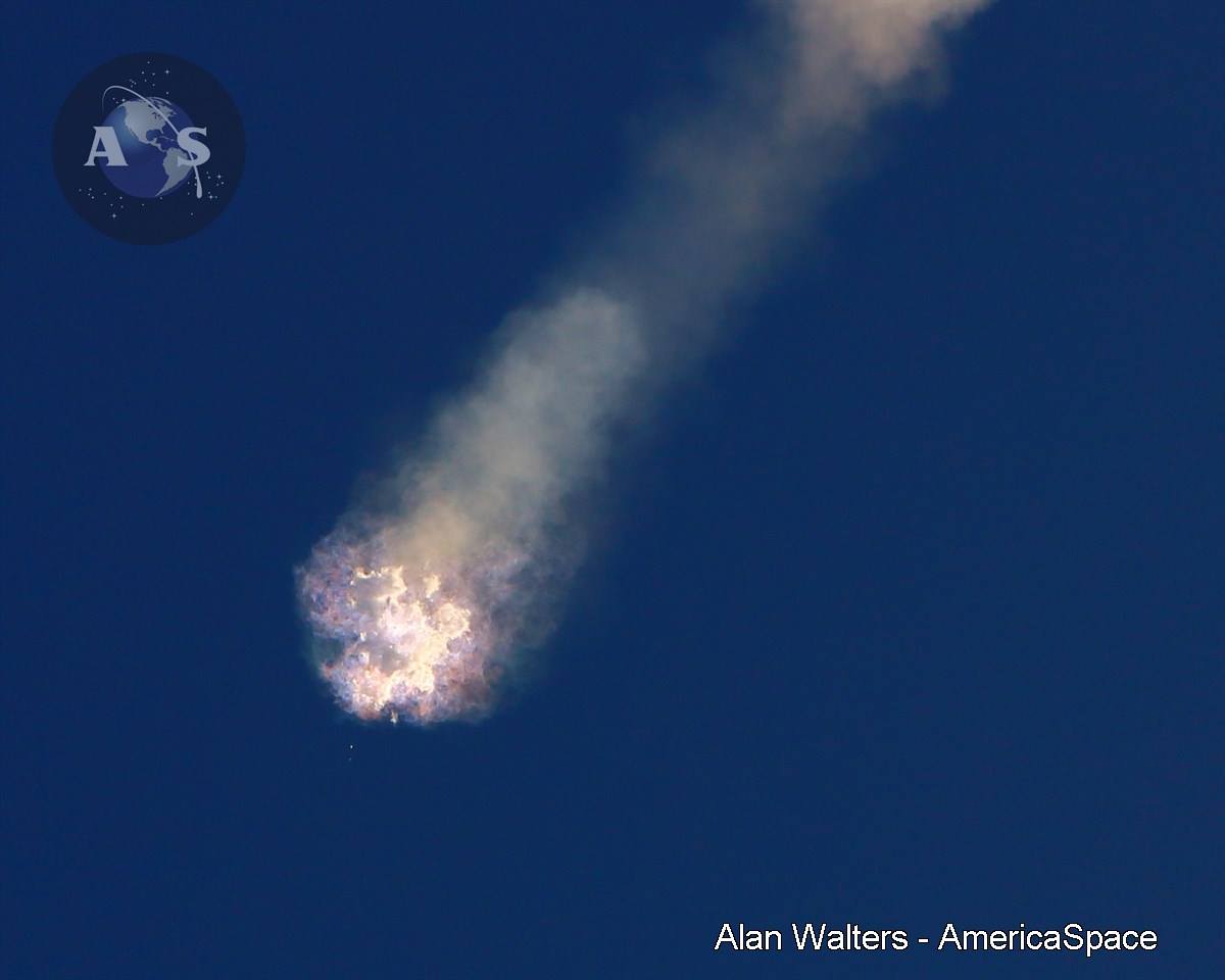
Though SpaceX has made great strides in aerospace science, like other companies, they too have faced setbacks and failures.  Most recently,  CRS-7 (cargo resupply) launched a Falcon 9 topped with an unmanned Dragon capsule destined to bring supplies to the International Space Station.  All statistics were considered nominal until 2 minutes and 19 seconds into the flight.  A cloud of vapor then formed outside the craft and a few seconds after, there was a loss of helium tank pressure.  This loss in pressure caused the tanks to explode and caused a complete failure of the mission.

The problem was attributed to a failed strut on the “helium pressure vessels” that broke due to the force of acceleration. This caused a breach and allowed helium to escape causing the demise of the spacecraft.

An issue with the software was also attributed to the problem as it caused the command to open the parachute for the Dragon capsule to never run, thus destroying most of the capsule.

This failure is the most recent mission failure and does not take into account the failed January 2016 attempt at landing the Jason-3 rocket on an autonomous barge in the middle of the ocean.

CRS-7’s failure and disintegration in mid air

On December 21st, SpaceX launched their first rocket since the failure that took place roughly six months prior.  In an article, Elon Musk wrote about important concepts such as gravity and velocity.

Many people tend to believe that gravity stops once you reach a certain altitude above Earth, after which you start floating around in “zero g”. The force of gravity “drops proportionate to the square of the distance between the centers of two objects.”

Musk also explains how this concept makes total sense when thinking about gravity wells like funnels — if you moved the marble 2% further away from the center of the funnel, it would still fall in, just very slightly slower.

Musk asks why astronauts in the space station, which is just under 400km in altitude (~90% of surface gravity), are floating around in what looks like zero g? He answers his own question by explaining that the space station is actually moving around Earth’s gravity funnel at “the blistering speed of 27,000 km/h (17,000 mph), completing a round-the-world trip every 90 minutes!”

He continues his explanation by stating that “the reason they are floating around is that they have no net acceleration. The outward acceleration of (apparent) circular motion, which wants to sling them out into deep space, exactly balances the inward acceleration of gravity that wants to pull them down to Earth.”

image of the ISS

Elon Musk and SpaceX have been prodding and poking at the limits of human capacity since its conception in the early 2000’s as they attempt to re-invent the wheel of space travel .  Their discoveries and continuous experimentation might lead to major breakthroughs in technology and space exploration.

Sources:

http://www.spacex.com/news/2015/12/21/background-tonights-launch

http://www.airspacemag.com/ist/?next=/space/is-spacex-changing-the-rocket-equation-132285884/

http://www.theguardian.com/technology/2013/jul/17/elon-musk-mission-mars-spacex

http://www.wired.com/2015/06/elon-musk-space-x-satellite-internet/

https://en.wikipedia.org/wiki/SpaceX

Robot Activity Blog

Robotics

Goal:

The goal of this activity was to test and ultimately compare the accuracy between human measurements and the measurements done by a computer program.  This was done by conducting various experimental trials and at the end calculating the margin of error between the computer and the manual results.

Robot used for experiments

“What did you actually do?”:

The experiment itself consisted of the robot or car that was used during the experiment, a USB cable, the computer program used to run the robot, and a ruler.  The experiment was quite simple, yet intriguing to do.  The robot was placed in a straight line on a smooth surface and the ruler was used to measure the distance the robot would travel from its starting point at different motor power levels.  Time was kept at one second throughout the experiment so that there would be no more than one variable during the experiment.  The robot’s starting point was from it’s axel and its end point was also measured at the axel.  During the activity, the group ran 3 experiments, each one consisting of three trials.  Each experiment had three different power levels for the motor.  Below are both the manual and computer calculations taken during the experiments.

Results:

Experiment #1:

Power Level: 75

Time: 1 Second

    Computer Calculations   Manual Calculations Margin of Error
Trial #1 Distance 0.27024 Distance 0.275 1.84%
Velocity 0.27024 Velocity 0.275
 
Trial #2 Distance 0.27024 Distance 0.27 0%
Velocity 0.27024 Velocity 0.27
 
Trial #3 Distance 0.27264 Distance 0.273 0%
Velocity 0.27264 Velocity 0.273

Experiment #2

Power Level: 70

Time: 1 Second

    Computer Calculations   Manual Calculations Margin of Error
Trial #1 Distance 0.253 Distance 0.257 1.57%
Velocity 0.253 Velocity 0.257
 
Trial #2 Distance 0.255 Distance 0.255 0%
Velocity 0.255 Velocity 0.255
 
Trial #3 Distance 0.255 Distance 0.256 0.39%
Velocity 0.255 Velocity 0.256

Experiment #3

Power Level: 80

Time: 1 Second

    Computer Calculations   Manual Calculations Margin of Error
Trial #1 Distance 0.298 Distance 0.294 1.35%
Velocity 0.298 Velocity 0.294
 
Trial #2 Distance 0.299 Distance 0.293 2.03%
Velocity 0.299 Velocity 0.293
 
Trial #3 Distance 0.299 Distance 0.295 1.35%
Velocity 0.299 Velocity 0.295

Conclusion:

In conclusion, the margin of error between the computer and our hand measurements were not too far off from each other.  Though it is only a fractional amount, there are definitely some factors that may have attributed to the slight differences.  Human error is undoubtedly the factor that may have affected the outcome the most, however, forces such as friction may have also played a smaller role.  The robot itself also tended to brake abruptly and often ended up a few centimeters back from where it originally stopped.  These jerks from the abrupt stops became stronger as the motors’ power levels increased.

The Grid

Electricity is delivered to your home through the grid — “a complex network of power plants and transformers connected by more than 450,000 miles of high-voltage transmission lines.”

The process from beginning to end can be seen in the figure below.

Simply explained, electric power is first generated at power plants.  It is then moved by means of transmission lines to substations.  A local distribution system of smaller, lower-voltage transmission lines moves power from substations to you, the customer.  In the process there are several transformers that steps down the voltage of the generated electricity before it enters the neighborhood distribution lines or your home.

Below is a video that also explains the grid and how it works.

America’s electric grid is made of three smaller grids, which are called interconnections.  These interconnections are what are responsible for moving electricity around the country. “The Eastern Interconnection operates in states east of the Rocky Mountains, The Western Interconnection covers the Pacific Ocean to the Rocky Mountain states, and the smallest — the Texas Interconnected system — covers most of Texas”

Below is an image displaying the areas covered by each interconnection.

The electric grid is an engineering marvel and was conceived over 100 years ago when electricity needs were simply.  Most homes had small energy demands such as a few light bulbs and a radio. However due to its age, the infrastructure requires continuous and extensive upgrades. Several acts have made it possible for billions of dollars to be invested in the modernization of the country’s electric grid.  Since 2010, the investments have been used to deploy many advanced devices such as capacitors and feeder switches.  However, there is a distinction between a reliable grid and a resilient one. A more reliable grid is one with fewer and shorter power interruptions. A more resilient grid is one better prepared to recover from adverse events like severe weather.  Due to its age, the U.S’ electric grid can be said to be neither.  Severe weather, such as various storms cause many power outages and costs the economy billions of dollars annually in “lost output and wages, spoiled inventory, delayed production and damage to grid infrastructure.”

To continue moving into the future, the United States needs a new kind of electric grid, one that can handle digital, computerized equipment, and technology that is dependent on it.  It is vital that the U.S has a grid that can handle the “increasing complexity and needs of electricity in the 21st Century.”

The smart grid is much like the Internet, and consists of controls, computers, automation, and new technologies and equipment that work together, but in this case, these technologies will work with the electrical grid to respond digitally to quickly changing electric demand.

A new electric grid can have both positives and negatives such as the ones listed below.

PROS:

  • More efficient transmission of electricity
  • Quicker restoration of electricity after power disturbances
  • Reduced operations and management costs for utilities, and ultimately lower power costs for consumers
  • Reduced peak demand, which will also help lower electricity rates
  • Increased integration of large-scale renewable energy systems
  • Better integration of customer-owner power generation systems, including renewable energy systems
  • Improved security

CONS:

  • Rebuilding the existing electrical grid will be time consuming and expensive.
  • The estimated cost of replacing the existing infrastructure is between $13 and $50 billion.
  • The real-time pricing of smart meters may negatively affect particular industries.
  • Utilizing the internet to provide real time grid data increases the risk of privacy and security breaches.

As the U.S’ need for electricity continues to grow, the need for a new electric grid will be more and more present.  The smart grid is but one method to modernize the U.S’ grid.  Regardless, major changes will need to be made to the grid in order for it to accommodate the exponential growth in energy consumption.

Sources:

http://securethegrid.com/the-basics-of-grid-security/

http://www.geni.org/globalenergy/library/national_energy_grid/united-states-of-america/americannationalelectricitygrid.shtml

http://www.heritage.org/research/reports/2014/10/americas-electricity-grid-outdated-or-underrated

http://www.theenergycollective.com/john-cooper/90021/intolerable-situation-outdated-paradigm

http://articles.latimes.com/2003/aug/15/business/fi-grid15

https://en.wikipedia.org/wiki/Electrical_grid

https://www.edf.org/climate/smart-grid-brings-us-power-21st-century